By insideSail
Published without technical review · version 3 ·
Leading line: alignment depends on where you observe
Two distinct marks can share a visual direction; this does not give distance.
In this guide
A visual alignment, or transit, relates marks on the same line: from certain positions they appear in the same horizontal direction. The front mark is nearer the observing side and the rear farther away.
When the observer moves laterally off that line, the directions separate. This visually identifies a geometric relationship, but alignment alone supplies neither distance to the marks nor a unique position.
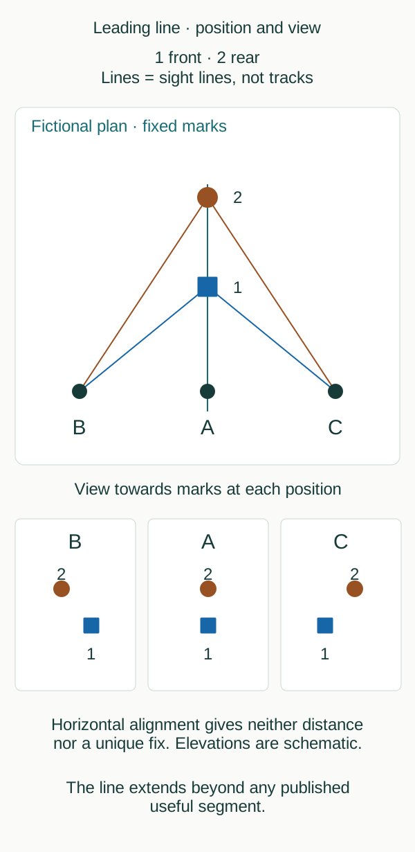
Original interpretation schematic with declared functions and references. No scale, approved installation or operational track.
insideSailOriginal insideSail artwork — all rights reservedEnlarge the diagram
Plan and observed view show different parts
The plan locates marks 1 front and 2 rear, together with three stationary observers. Lower panels show the horizontal relationship seen by each observer.
At A, front and rear align horizontally. They may still appear at different elevations, as is usual where the rear has suitable height.
Sharing the same vertical plane does not require the two objects to obscure each other completely in the view.
The drawing’s colours distinguish the two marks only. They are not the red/green code of a lateral mark.
For a leading alignment, the authority selects suitable features that distinguish marks from the background. Published identity and function matter: two windows or buildings that happen to line up in a view do not automatically become an established leading alignment.
Worked case: the observer on the left
- Join B to the front mark with a sight line.
- Join B to the rear with another sight line. The rear is farther away on the same mark line.
- Compare directions in plan: the front sight line inclines farther right.
- Read panel B: front appears right of rear. At C, on the opposite side, the relationship reverses.
| Position in figure | Observed horizontal relationship | What the reading establishes |
|---|---|---|
| A, on line | Front and rear aligned | On the illustrated extension |
| B, left | Front right of rear | On one side of the line in this geometry |
| C, right | Front left of rear | On the opposite side in this geometry |
The difference arises because the marks are at different distances: lateral displacement affects direction to the nearer object more. If the image is rotated or mirrored, or viewed from beyond the marks, the geometry must be reconstructed.
Memorising “front to the right” without stating viewpoint removes the reference that makes the phrase meaningful. The figure links each position with its view to retain that information.
Alignment does not measure distance
Imagine A nearer and then farther away while remaining on the same extension. The marks remain horizontally aligned but distance changes.
Several possible positions produce the same visual relationship. Apparent vertical separation may change too, but the figure supplies no elevations, scale or distance method.
Determining a position requires additional appropriate information and assessment of its accuracy and geometry.
A geometric line and the published segment
A geometric line extends indefinitely, but its useful segment has limits and a purpose. IHO S-4 distinguishes a navigable track from the remaining extension.
An alignment can also delimit a condition rather than be a line to follow: charts and documentation establish its function. Alignment alone resolves neither depth, obstacles nor restrictions.
Consult published purpose and extent before assigning operational meaning to the visual relationship.
English terminology distinguishes a transit, the visual relationship between aligned objects; a leading line, a published navigable lead; and a clearing line, an alignment defining a danger boundary. In IHO usage, leading lights is reserved for a lead to follow; lights in line may identify a limit.
The same visual geometry serves different functions that the legend and documentation must declare.
- Front and rear are relative to the stated observing side.
- Horizontal alignment allows different apparent elevations.
- Observer position determines separation of sight lines.
- Correct identity, function and published segment complete the geometric interpretation.
Sources and references
- RBMN — artigo 14: Boias de assinalamento de emergência ↗
Diário da República · RBMN annex Article 17; printed p.1981, PDF p.4.
Annex RBMN Article 17, published text 24 June 2016. Commencement follows Portaria Article5; later national interpretation/updates and local directions require qualified checking. Not treated as automatic adoption of IALA2023.
Checked on - Regulations for International (INT) Charts and Chart Specifications of the IHO — S-4 ↗
International Hydrographic Organization · B-460–B-466 buoy characteristics; B-471 light descriptions; B-475.1–B-475.6 sectors and leading lights; PDF pp.306–331 and 336–339. B-132/B-132.1–3, PDF59–60: true clockwise bearings, sector/leading bearings from seaward, reciprocals. B-433.1–3, PDF233–234: marks, legends and navigable versus remaining lead; B-475.6, PDF339 cross-reference.
Official 452-page PDF directly consulted; edition verified against current IHO catalogue. Original educational fragments rather than reproduced INT1 symbol plates. Paper chart conventions are not universal electronic display behaviour. Exact additional passages directly read from official freshly fetched March2026 edition; existing source/regulatory records unchanged. Original reference geometry is not a chart or engineering approval.
Checked on - IALA R1001 — Lighthouses, leading lines, sector lights and other aids ↗
IALA · Sections 2.7.1–2.7.6; PDF p.21 onwards; edition 2.0 June 2023.
IALA recommendation, edition 2.0 June 2023, 2.7.1–2.7.6. Consulted edition does not establish individual national effective dates. Publication and jurisdiction require qualified review.
Checked on
Regulatory references
- RBMN artigo 17 — Enfiamento e alinhamento ↗
Portaria 177/2016, original published annex · Defesa Nacional e Mar; technical direction Direção de Faróis / DGAM · Portugal
Verified on - S-4 B-460–466 / B-470–475 — buoy and light charting specifications ↗
IHO S-4 edition 4.10.0 March 2026 · International Hydrographic Organization · International chart-production specification; not a local pilotage rule
Verified on - Lighthouses, leading lines, sector lights and other aids ↗
IALA R1001 edition 2.0 June 2023 · IALA · International recommendation; competent-authority implementation
Verified on
Keep discovering
The next piece of the puzzle
Discuss this concept
Loading the conversation…