By insideSail
Automated technical check · version 2 ·
One hull in plan, profile and section
A view reveals two dimensions; other relationships need another drawing.
In this guide
A side silhouette is recognised as a boat yet reveals little about width at each position. A plan can show the outline from above while leaving depth unresolved.
A section adds the width/height relationship at a selected cut. Combining those views makes shape understandable without confusing drawing with construction.
A simplified fictional solid lets us follow the three views of the same object. Each view is a way to organise information, and none is a substitute for the missing dimensions supplied by the others.
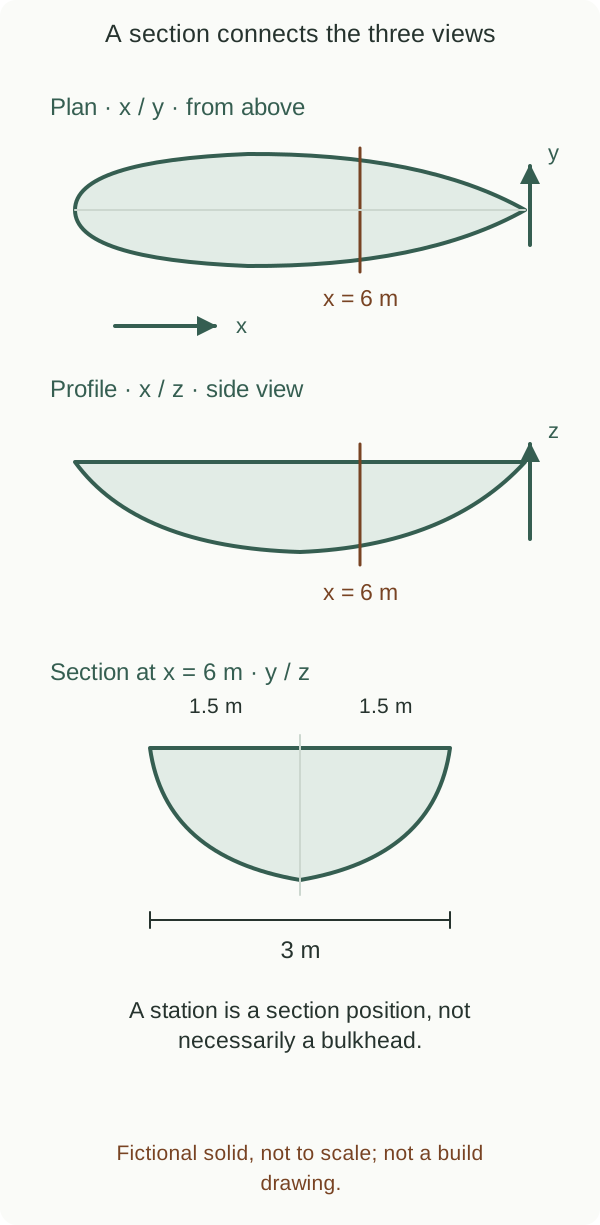
Fictional solid, not to scale; not a build drawing.
insideSailOriginal insideSail artwork — all rights reservedEnlarge the diagram
First declare the three axes
In our exercise, x follows length, y follows width and z follows height. Plan shows x/y, side profile shows x/z, and the selected transverse section shows y/z.
The legend declares that convention. Other authors may choose different origins and signs.
Do not infer port, bow position or relative height solely from where an arrow appears on a page. The orientation lesson’s references still belong to the boat.
The drawing should also state its viewing direction, so that turning a sheet over does not silently change the interpretation of its sides.
Projection is not cutting
An exterior plan is a projection: points at different heights can overlap in the same place on the view. A section is a different operation, selecting the shape’s intersection with a plane.
A geometric waterline results from a horizontal plane at a declared height and is not necessarily the actual free surface around a floating boat. Likewise, a top-view deck outline is not automatically beam at the waterline.
Identifying the operation prevents these quantities being exchanged merely because their curves look similar or share the word “plan”.
A hull-form representation uses several sections along the length to show changes hidden by a single central cut. Stations identify those positions under the drawing’s convention.
The MIT teaching example organises sections, waterlines and coordinate tables as related information. We use that principle without adopting its vessel values.
A narrower section at one station does not establish a narrow hull everywhere. Nor does a geometric section independently depict a bulkhead: its plane can cut a place containing no physical partition.
This separates an imaginary analytical slice from an actual structural component.
Read a change in its corresponding views
In the fictional solid, a cut at x=6 m has total width 3 m at a chosen height. The corresponding horizontal intersection has half-width 1.5 m on each side of the centreline.
Profile places the same station at x=6 while revealing no width there. These invented values check correspondence without establishing displacement.
Record different units or scales if used in separate views. A screen-stretched image can look fuller even when no coordinate has changed; do not measure the displayed outline as though the page were a dimensioned, scale-preserving drawing.
What a hull-form drawing does not promise
Geometry can support analysis when suitable data and methods exist, but our sketch calculates neither stability, resistance nor wave behaviour. ORC explains how sections participate in hull representation.
Shape, material and connections are different information: the same exterior curve identifies neither thickness nor what lies inside. Preserve the document identity and what it actually depicts: configuration, hull lines, an interior arrangement or a photograph.
Reading becomes more accurate when you can name both the view and the question it does not yet answer. Learning to request the missing view is progress without pretending to perform naval architecture.
- Plan, profile and section reveal complementary relationships.
- A geometric section is not automatically a physical boat component.
- Exterior shape, interior space and structural analysis are different information.
Sources and references
- Hull geometry ↗
Offshore Racing Congress · Opening explanation: sectional points/offset representation; proprietary geometry restriction.
Public selected explanation read. No proprietary offsets obtained; all lesson coordinates represent an original fictional solid, not a real-model hull.
Checked on - 13.400 Introduction to Naval Architecture — Project1 Ship Hydrostatics ↗
Massachusetts Institute of Technology · Three-page assignment, pp.1–3: half-breadth/profile/body plans, stations, waterlines and geometry before hydrostatics.
Official PDF downloaded and all three pages read. Only geometric organisation used; no USS Olympia offsets, line artwork, structural design, sea-kindly-period recommendation or prescribed integration task reused.
Checked on
Keep discovering
The next piece of the puzzle
Discuss this concept
Loading the conversation…