By insideSail
Automated technical check · version 2 ·
Blocks: effort and line travel in an ideal model
Less effort creates no energy and establishes no fitting capacity.
In this guide
Following a line identifies purpose, but understanding a purchase also requires distinguishing each component’s movement from total line travel. A fixed block can change pulling direction without multiplying the ideal force applied to the moving part.
An arrangement with a moving block can distribute force through several supporting line segments. Visible sheave count alone does not establish the ratio.
This lesson uses desk diagrams with explicit assumptions and no actual loaded equipment. It explains a relationship rather than instructing anyone to assemble, select or certify a tackle for a boat.
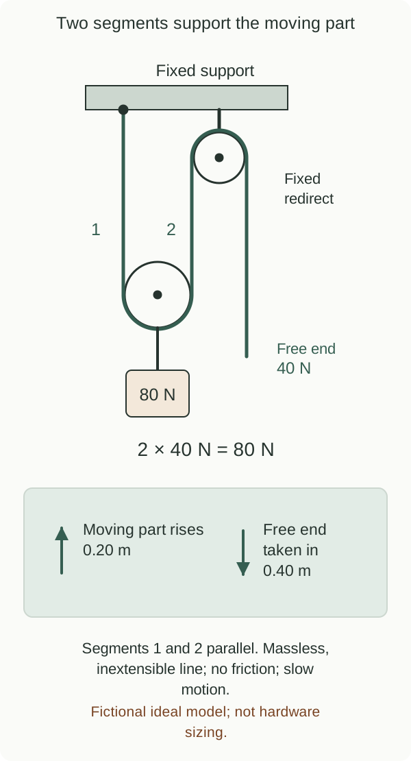
Fictional ideal model; not hardware sizing.
insideSailOriginal insideSail artwork — all rights reservedEnlarge the diagram
Start with what moves
Mark a fixed assembly and a moving one in the drawing. Follow one continuous line from its anchored end to its free end.
In a direct ideal 2:1 arrangement, two parallel segments support the moving part. If it rises 0.20 m, each shortens by 0.20 m, requiring 0.40 m of line to be taken in.
That length relationship can be understood before introducing forces. An additional fixed block redirecting the free end can leave it unchanged.
This explains why two photographs with different numbers of visible blocks may still describe the same ideal displacement ratio.
The ideal calculation conserves work
Assume a massless, inextensible line, negligible friction and slow motion without relevant acceleration. Tension is equal along this ideal line.
With two parallel supporting segments, their combined force on the moving part is twice one segment’s tension. Against a fictional resistance of 80 N, ideal free-end force is 40 N.
Moving the resistance 0.20 m requires 16 J; applying 40 N over 0.40 m also gives 16 J. Energy has not been gained.
These numbers are invented for the diagram and represent no sail load or manufacturer working-load limit.
The relationship in numbers
Ideal 2:1: F = R ÷ 2; line taken in = 2 × displacement
Forces in N; distances in m; work in J. Parallel segments; losses neglected.
More purchase, another travel distance
A direct ideal 4:1 model with four supporting segments takes in 0.80 m of line when its moving part travels 0.20 m. Ideal force against the same 80 N resistance is 20 N.
The comparison reveals two simultaneous consequences: less effort and more line to manage. It establishes neither a person’s ability to operate real equipment nor a faster response.
Seldén documentation describes this force/travel trade-off, but its product examples are not transferred into the exercise. A higher ratio can change the quantity of line needed even when the required movement remains the same.
Friction, bearings, angles, elasticity and line condition affect the real result. An inclined segment contributes only part of its tension along the chosen movement direction.
Cascaded purchases need stage-by-stage analysis rather than counting every visible line. A jam does not mean the ideal ratio has become mathematically wrong: routing or condition may introduce a question outside the model.
The representation helps understand limits rather than justify pulling harder. A reported effort on a real boat therefore cannot be compared directly with the ideal result unless its actual configuration and conditions are known.
Line tension is not the load on every component
Fixed attachments, sheaves and the moving assembly receive different force combinations. A redirecting block’s attachment load depends on line directions.
“I only pull with 20 N” does not establish the required capacity of every component. Manufacturer information distinguishes product load from line load.
Force is also not mass: the newtons used here should not be converted into kilograms of product without stating the quantity involved. Selection and human suspension are outside the exercise.
Understanding mechanical advantage is useful precisely when it prevents a reduced hand effort being mistaken for a reduced load everywhere.
- Ideal purchase trades effort for travel rather than creating energy.
- Count relevant segments after identifying the moving body.
- A fitting’s load is not automatically the free-end tension.
Sources and references
- Deck Hardware — 595-905-E, Version 12 ↗
Seldén Mast · Printed/PDF p.6 Purchase systems; distinct line/product loads; restriction against human suspension.
Official 114-page PDF downloaded; entire selected p.6 read. Source uses kg load shorthand; our fictional ideal calculation uses forces in N. No product ratings, selection method, rigging diagram, prescribed effort or manufacturer artwork reused.
Checked on
Keep discovering
The next piece of the puzzle
Discuss this concept
Loading the conversation…