By insideSail
Automated technical check · version 2 ·
Following a line: name, path and purpose
A line can change direction without changing its job.
In this guide
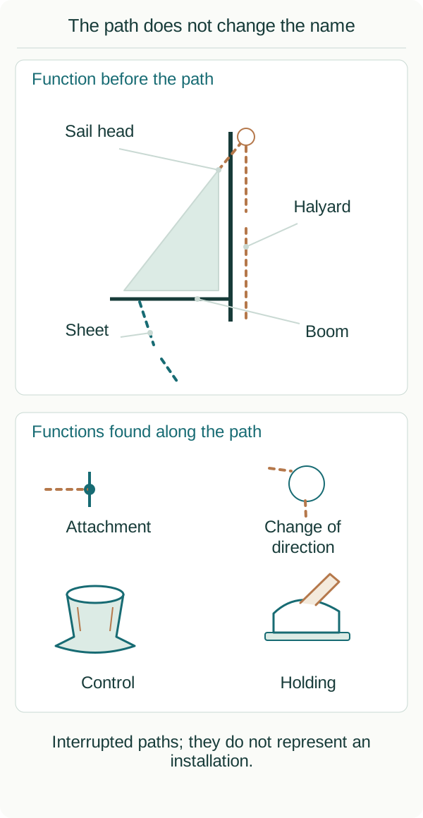
Interrupted line sections and independent functions. This is not an installation route or operating sequence.
insideSailOriginal insideSail artwork — all rights reservedEnlarge the diagram
When following a line in a drawing, bends can attract more attention than purpose. Begin with the job associated with the line.
A halyard relates to hoisting a sail; a sheet to controlling a sail. The path can include fittings and changes of direction.
Its functional name does not change at every point. This figure is conceptual and omits installation connections; it is not a path to reproduce aboard.
The line retains its purpose between points
A halyard relates to the upper area of a sail used in hoisting it. Its path can change direction around sheaves before reaching the control area.
A sheet relates to sail control and, depending on the arrangement, can connect to the sail or boom assembly. Following the drawing means recognising these relationships rather than renaming the segment after each bend.
Imagine one highlighted line travelling up towards the sail and returning to a lower area through a direction-changing element: both drawn lengths can belong to one line. The figure still describes one job despite showing several segments.
Where an assembly has more passes, counting drawn lengths does not equal counting independent lines. A continuous path and functional key clarify identity.
Material, construction and product reference add other inventory fields; they do not replace the relationship between line and job. This makes the schematic intelligible before a particular installation’s components or operational sequence are introduced.
Purpose belongs to the whole description
Seeing a line near a sail is insufficient to name it. It may belong to another control or merely be stowed there.
An identified drawing or documented caption adds its job. In an inventory, “mainsail halyard” differs from material, diameter and manufacturer.
Each field adds detail without replacing the others. The central halyard-and-sheet lesson retains those definitions; here we apply them to a path.
Points, components and controlled object
The diagram distinguishes controlled object, change of direction and a control or holding area. Symbols represent roles rather than prescribe fittings.
Components may lie between points simplified by the drawing. An arrow follows the reading of the path, not an allowable force or an instruction to pull.
That caption matters: without it, an educational line could look like a complete installation drawing.
| Information | Fictional example | What it cannot establish |
|---|---|---|
| Job | Sheet for an identified sail. | Material or capacity. |
| Path | Passes a change of direction. | A component suitable to copy. |
| Colour | Line highlighted in copper. | A universal functional colour code. |
| Product | Reference recorded in the inventory. | Suitability of a similar reference. |
Worked example: one halyard in two images
Now imagine the caption is missing. Similar colour may suggest a relationship but does not establish it.
Two lines can share a colour, and one line can look different under changing light or photography. The description becomes “line visible in this area, job unconfirmed”.
That is useful information because it retains an observation without inventing identity. A sequence of photographs resolves the doubt only if the relationship can actually be followed or documented.
Construction and purpose remain separate
Core-and-cover and other rope constructions may appear in control descriptions. Actual selection depends on application and system, a different subject from this map.
“New”, “strong” or “low stretch” need a reference; they do not define the job. The material-and-construction lesson organises properties once rather than letting every path create another explanation of the same product.
A path description does not explain operation under load. Knowing where a line runs does not teach clutch release or winch use.
That separation makes the lesson useful before practical learning: you can recognise elements mentioned in an explanation and identify missing documentation. A clearer map of names and relationships produces more specific questions about the actual assembly.
Three things to remember
- A functional name does not change at every bend.
- Path, colour and construction are separate information.
- A conceptual map is neither an installation nor an operating sequence.
Sources and references
- Hints and Advice on Rigging and Tuning ↗
Seldén Mast · Printed pp.6–7 Rig types; pp.8–9 Longitudinal rigging; pp.10–11 Lateral rigging; pp.12–14 Running rigging; p.56 Booms.
Official 92-page PDF retrieved and the stated sections consulted. Edition year not inferred. No tuning procedures or protected figures reproduced.
Checked on - Plain bearing blocks ↗
Seldén Mast · Applications; Features PBB 70/80; component variants.
Product identity and vocabulary only; load ratings and installation suitability are not adopted.
Checked on - XAS — rope clutch ↗
Spinlock · Product Info; Specification; Documents — instructions, holding table, drill guides.
Product-specific documentation example; no capacity, price or compatibility recommendation.
Checked on
Keep discovering
The next piece of the puzzle
Discuss this concept
Loading the conversation…