By insideSail
Published without technical review · version 2 ·
A loaded line: direction, extension and energy
Strength and stiffness answer different questions; geometry influences what a line restrains.
In this guide
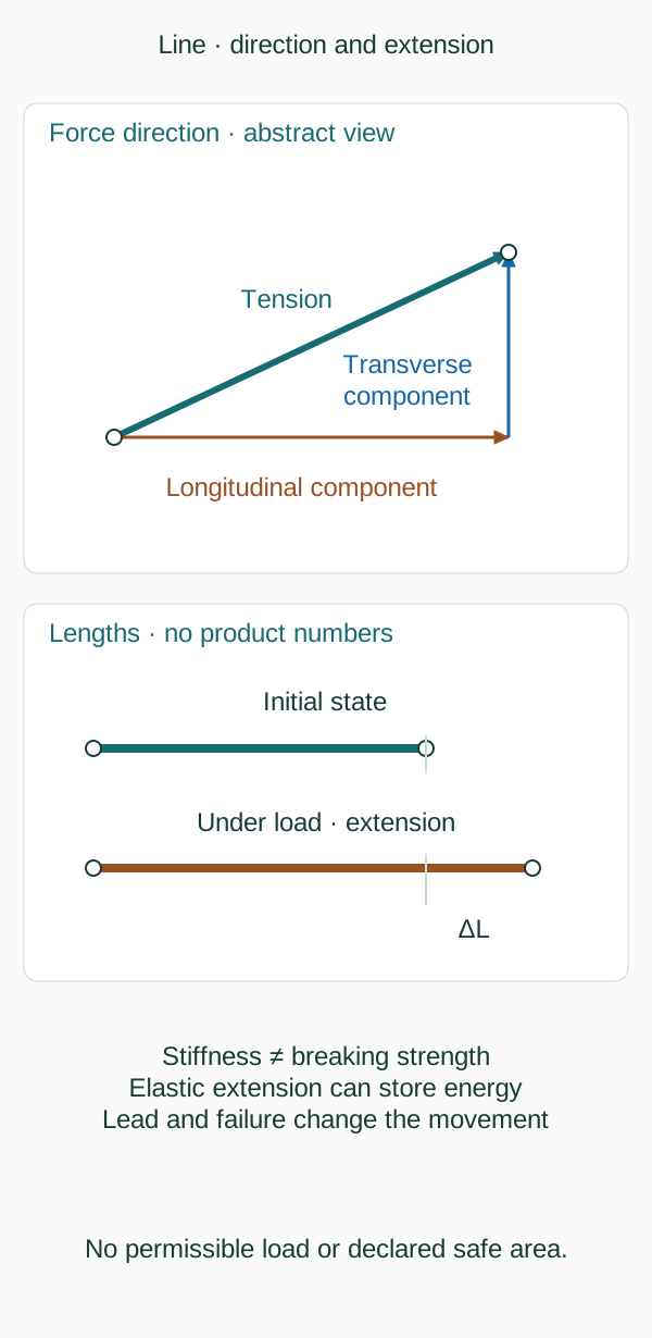
Original conceptual schematic, not to scale; fictional cases, not a manoeuvre procedure.
insideSailOriginal insideSail artwork — all rights reservedEnlarge the diagram
A line pulls along its lead
A loaded line transmits force along its lead between supporting points. In a plan view, a diagonal line can have longitudinal and transverse components relative to the boat.
This explains why the same tension can restrain motion differently according to direction. The figure selects no attachment points: it shows an abstract segment separating force direction from vessel dimensions.
Where a lead changes at a fairlead or fitting, force directions on that fitting change too. The system cannot be assessed by looking at one straight portion alone.
Cleats, guides, supports and structure receive loads depending on geometry and loading. A complete layout is deliberately omitted: a drawn arrangement without capacities and verification could be mistaken for a recommended mooring solution.
Strength is not stiffness
Strength relates to capacity to carry load before failure under defined conditions. Axial stiffness relates to resistance to extension under load.
Two ropes with similar breaking strengths may extend differently. Conversely, selecting the least extensible rope proves neither greater strength nor suitability.
Comparison needs product, diameter, material, construction, condition and purpose rather than a fibre name alone.
Samson distinguishes extension components and presents EA as a stiffness description for its products. That does not permit a universal value to be assigned to nylon, polyester or HMPE without the actual rope.
Elastic extension, constructional bedding-in and time-dependent deformation are not synonyms either. The figure uses an initial and an altered length only, without percentages, a test curve or recommended working load.
Stored energy and release
Elastic extension under force can store energy. Sudden release can produce recoil and movement of system parts.
At the same load a more extensible rope may store more energy, but real assessment also depends on length, additional elastic elements, lead and failure mechanism. Saying a fibre has low extension does not make the system incapable of dangerous movement, especially where other parts store energy.
MCA guidance also highlights bights and snap-back risk. A person inside a bight may be struck or drawn in when it closes under tension without the rope breaking.
No small red patch is drawn with everything else labelled safe: changes of lead and failures can alter motion. The Zarga case specifically demonstrates limits of a previously designated safe area.
Understanding the mechanism improves questions
Observations of wear, colour change or deformation should be linked to rope identity, location and date. A photograph cannot turn appearance into residual load capacity.
Safety must not be tested by pulling with people nearby or improvising a proof load. Inspection, retirement criteria and suitability belong to manufacturer guidance and competent assessment.
This example explains mechanisms without setting replacement intervals for every product.
Rotating the reference axes in the abstract segment does not alter the existing tension: it changes how tension is resolved. Components have meaning only with declared references.
The drawing chooses a horizontal longitudinal axis and vertical transverse axis for readability; that does not mean an actual boat must face that way at a berth or a line must follow that lead. It is a decomposition, not an arrangement.
Useful reading distinguishes tension, directional components, stiffness, strength and energy. These words are not five ways of saying strong.
Industrial sources support principles and hazards rather than transferring commercial-ship procedures to a yacht. Assembly, sizing and operation of a loaded system require information and capabilities absent from the abstract diagram.
Sources and references
- Elastic Stiffness — technical bulletin ↗
Samson Rope Technologies · Overview; Changing the way we express elongation; EA/material/construction distinctions; no product tables reproduced.
Manufacturer primary explanation, not neutral product ranking. No strength selection, safety factor or working-load value recommended.
Checked on - Mooring Lines With Reduced Recoil Properties — Design, Analysis and Standardization ↗
Samson Rope Technologies · Five-page manufacturer paper; PDF pp.1–2, Introduction and A. Energy Absorption: load/extension and length context.
Primary historical technical paper directly read for elementary energy principles only. Its draft CI1502 status, tests, commercial design and claimed warning times are not asserted as current standards or yacht recommendations.
Checked on - MGN 592 (M+F) Amendment 2 — anchoring, mooring, towing or hauling equipment ↗
Maritime and Coastguard Agency · Sections 4.1–4.6 system loads and line direction; 5.1–5.5 bights and snap-back, whole-area risk and redirected leads.
Official guidance directly consulted for hazards and geometry; commercial procedures, turns, stoppering methods and loads not imported as yacht instructions.
Checked on - Failure of mooring line on board LNG carrier Zarga with 1 person injured ↗
Marine Accident Investigation Branch · Investigation 13/2017 landing-page summary: designated safe area within snap-back zone; assessment and system failures.
Industrial-vessel incident used only to support limits of generic safe-zone drawings, not to prescribe yacht layouts.
Checked on
Keep discovering
The next piece of the puzzle
Discuss this concept
Loading the conversation…