By insideSail
Published without technical review · version 2 ·
Fenders: protection depends on contact
A fender separates surfaces only while remaining where those surfaces approach each other.
In this guide
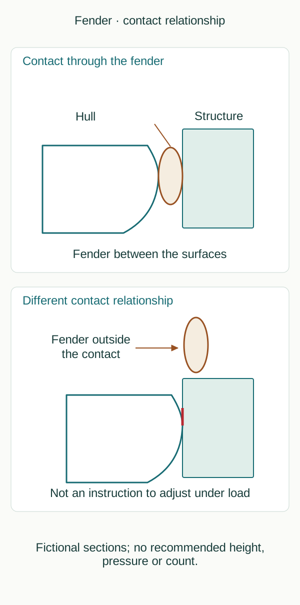
Original conceptual schematic, not to scale; fictional cases, not a manoeuvre procedure.
insideSailOriginal insideSail artwork — all rights reservedEnlarge the diagram
The function begins between two surfaces
A fender is a protective element placed between surfaces that may approach and compress together. Its function is not to prevent all vessel movement or replace mooring lines.
Hull, berth structure and fender form a contact relationship. A fender visible in a photograph may be outside that relationship: hanging beside the boat does not prove it intercepts the approaching surfaces.
The figure shows simplified hull and structure sections. One panel has contact through the fender; another has the fender outside the contact zone.
These are not height-selection instructions. Contact depends on hull geometry, quay edge, projections and relative motion.
A height appropriate to one situation may no longer correspond to contact after water level or vessel position changes.
Moving together is not moving identically
Beside a fixed quay, a boat rising or falling with the water changes height relative to the quay. Beside a floating pontoon, both may follow mean water-level changes but not necessarily the same instantaneous motion.
A boat may roll or move with a wave while the pontoon responds differently. Confusing these situations can make a changing relationship seem constant.
Movement can also be longitudinal or transverse. A cylindrical fender may roll, shift or cease to lie between surfaces depending on support and motion.
A local projection creates different contact from a broad regular face. The figure does not reproduce a product’s actual compression; it draws relative position to show why contact must be observed rather than merely assumed.
The product has limits too
Shape, dimensions, material and manner of use influence fender response. Inflation pressure, suspension points and maintenance instructions belong to the particular product.
A manufacturer’s sizing table is not transferred into a universal rule based only on boat length. Displacement, exposure, surfaces and motion can change the situation.
Having several fenders does not automatically establish that every important contact is covered.
Polyform presents its guide as general advice dependent on boat and conditions. One relevant observation is that a fender can swing onto the dock instead of remaining between dock and hull.
This physical mechanism is used rather than its complete commercial arrangement. Nor does the drawing select pressure, a minimum count or a structural suspension point without suitable assessment.
Recognising contact does not justify using the body
A person must not try to replace a fender with hands, feet or the body between the hull and another surface. Motion and mass can create crushing without a clear warning.
Seeing that a fender misses the contact zone is an observation to communicate and manage competently, not permission to enter a pinch area. Risk analysis must include anyone approaching while observing or trying to resolve the problem.
Contact may involve a small projection absent from a general berth view. Two surfaces looking similar at a distance can behave differently at that point.
A description should therefore identify the observed contact location without deriving compression or capacity from fender colour. The schematic simplifies surfaces to teach the relationship; it does not assume all quays are smooth or that an unresolved projection is harmless.
To document a case, describe surfaces, relative position, motion and product while separating observed state from prediction. A static photograph can establish a relationship at that instant, not the full range of tide or motion.
The educational gain is understanding where contact occurs and what changes it. Sizing and arranging actual protection still require knowledge of the berth, vessel and material limits.
Sources and references
- Boat Fender Guide ↗
Polyform US · General-guide qualification; Fendering tips; protection between hull and dock and risk of swinging onto dock.
Manufacturer advice within its product context. Sizing/count/pressure/line-diameter tables and configurations not reproduced or generalised.
Checked on - MGN 592 (M+F) Amendment 2 — anchoring, mooring, towing or hauling equipment ↗
Maritime and Coastguard Agency · Sections 4.1–4.6 system loads and line direction; 5.1–5.5 bights and snap-back, whole-area risk and redirected leads.
Official guidance directly consulted for hazards and geometry; commercial procedures, turns, stoppering methods and loads not imported as yacht instructions.
Checked on
Keep discovering
The next piece of the puzzle
Discuss this concept
Loading the conversation…